- Posted on
- Thijs Afman
Energy Management System (EMS) as the Beating Heart of the Smart Energy Hub

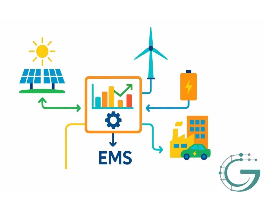
In a Smart Energy Hub, local generation (solar, wind), storage (batteries, hydrogen), and demand (commercial sites, heat pumps, EV chargers) converge. It is not a passive metering tool but the active brain that governs real-time energy and power flows. A hub “continually selects the optimal option for each moment, taking into account fluctuations in supply and demand.” Indeed, a Smart Energy Hub has been called “a game-changer in energy management, designed to balance local generation, storage, and consumption.” The EMS is literally its heart: the EMS control board continuously ingests data from PV arrays, wind turbines, batteries, inverters, and loads, then optimizes everything based on price signals and production forecasts. In doing so, an EMS goes far beyond simple monitoring: it actively controls when and how energy is charged, discharged, or consumed locally, thereby maintaining network balance.
Essential Technical Functions of the EMS
Real-time Control & Monitoring
The EMS continuously collects performance metrics (voltage, current, state of charge) from every source and sink. When deviations occur—such as a sudden spike in demand—it immediately intervenes (for example by curbing power output at peak times) to keep the system stable.
Market Optimization (Time-of-Use Arbitrage)
The EMS schedules charge and discharge cycles based on electricity price forecasts. It stores energy during low-price periods and releases it during expensive peak hours, lowering overall energy costs. This arbitrage strategy also eases congestion on the grid by smoothing out consumption patterns.
Load Balancing & Peak Management
By flexibly adjusting both storage and demand, the EMS can shave peaks. For example, it may discharge batteries during peak hours or temporarily scale back non-critical loads. In this way, the EMS mitigates grid peaks and helps preserve overall network stability.
Reactive Power Control & Grid-Code Compliance
An EMS also regulates reactive power—via inverters or static compensators—to support grid voltage. Grid codes mandate certain power-factor behavior and voltage-support functions under fault conditions. The EMS ensures these technical requirements are met through automatic VAr management and direct communication with network operators.
A modern EMS may simultaneously oversee dozens to hundreds of devices in a hub. It continuously monitors voltage, current, and state-of-charge across the battery farm and inverter network. When any parameter falls outside its acceptable range, the EMS instantaneously adjusts charge/discharge commands. In this role, the EMS serves not merely as a data logger but as an autonomous controller that safeguards grid balance under ever-changing weather and load conditions.
Cybersecurity, Version Control & System Integration
Cybersecurity
EMS platforms blend IT and SCADA functions, making them prime targets for cyberattacks. Recent industry reports show a 70 % increase in attacks on energy companies. Moreover, many field devices still rely on legacy protocols (e.g. Modbus, IEC 60870-5-104) that lack robust security. Encryption, network segmentation, strong authentication, patch management, and certificate governance are therefore indispensable to eliminate vulnerabilities. Unpatched inverters or open ports can otherwise lead to operational disruptions or data breaches.
Version Control & Process Management
An EMS comprises complex software and firmware. Professional version control (Git, CI/CD pipelines, A/B testing) is critical for tracking changes and enabling reliable rollbacks. Without strict configuration management, updates risk causing unexpected failures. Best practices—modular code, automated tests, and rollback procedures—ensure that each new release remains stable and reproducible.
System Integration
A hub’s EMS must integrate heterogeneous equipment—PV arrays, wind turbines, batteries, electrolysers, heat pumps, EV chargers, and more. Integration challenges can arise when conflicting control logics compete. For instance, one subsystem may initiate charging in response to an over–frequency event, while a market-signal simultaneously commands discharging, neutralizing both actions and jeopardizing grid stability. Likewise, poorly coordinated feedback loops can produce oscillations. Addressing these integration issues requires explicit conflict-resolution logic and priority schemes within the EMS.
Design, Testing, Operation & Scaling
A robust EMS implementation follows a structured lifecycle:
- Design & Specification
Define all functional requirements—hardware architecture, communication topologies, fail-safe mechanisms, and interactions with grid codes. Industry frameworks (e.g. SGAM, IEC reference architectures) often guide the modeling of EMS functions. - Simulation & Prototyping
Conduct extensive testing in simulated environments. Hardware-in-the-loop (HIL) setups model both controllers and a virtual grid, enabling validation under simulated faults and boundary conditions. Only after rigorous validation does the platform proceed to field integration. - Commissioning
Deploy the EMS in controlled pilot installations, followed by gradual introduction into the live grid with restricted authority. Engineers fine-tune control parameters, verify all protective interlocks, and validate reporting functions. - Operational Management
Once live, the EMS is continuously monitored via dashboards and alerts. Faults—overvoltage, thermal anomalies, communication errors—are logged and prioritized. Regular firmware and software updates via version control enhance performance, while phased roll-outs introduce new control strategies. Predictive maintenance—driven by EMS analytics—ensures timely replacement of critical components. - Scaling Out
A proven EMS platform can be replicated across multiple sites. Modular architecture and cloud connectivity enable efficient reuse. Standardized integration blueprints make successive deployments predictable and cost-effective.
In practice, only this integrated methodology can reliably coordinate all energy flows. A well-engineered EMS transcends mere monitoring: it actively addresses grid congestion and manages complex hubs as a single, cohesive system—exactly what is needed for the next phase of the energy transition.
